
0 / 16
LED Blink: HIGH, LOW & Delay
Run an Arduino LED blink experiment. Compare 500 ms and 1000 ms delays, follow D13, and calculate the full on-off cycle.
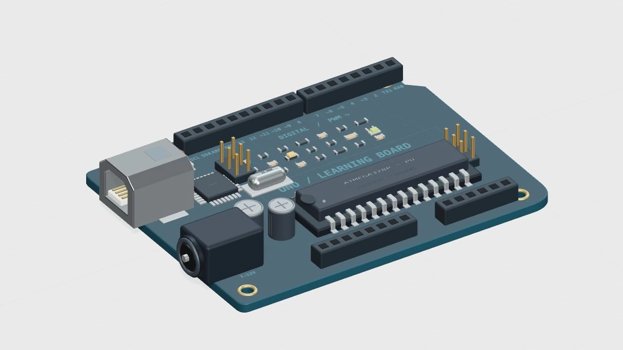
Preparing the 3D view. Experiment controls are already available.
3D is unavailable on this device. Circuit view and simulation controls still work.
Ready to explore
SIGNAL TRACEWaiting to run
Component directory · select to locate
No matching parts. Try a component name or pin number.
Numbers match model markers. Select a part for its function, connections and controls. With the model focused: Q/E rotate, WASD pan, +/− zoom, R reset, Esc returns.
CODEUNOLED
Experiment controls
Change one thing. Make a prediction, then run it.
sketch.ino
| Pin | Connects to |
|---|
Signal-path reference only. Verify component documentation for physical wiring.
Signal monitor
Run the experiment to watch inputs and outputs here.
Guided simulation · not a C++ compiler
Your experiment
Make the light stay on twice as long as it stays off.